Debug connector
It’s often needed to connect a SWD debugger to a board.
We found Black Magic Probe to work well, for a variety of MCUs, and it doesn’t require openocd. You can use their beautifully made hardware, or flash an existing board with Black Magic firmware. People also often use ST Link v2 clones, especially for STM chips.
One way or another, you need to connect the SWDIO and SWCLK lines from the debugger to the MCU. Often these are connected to test pins, to which you have to solder. Sometimes there is a standard 0.05” 10 pin ARM debug connector, however these require a part to be soldered on the board. Otherwise, people use a footprint on the PCB to which they connect a special proprietary (and expensive) connector cable.
Here we propose two simple and cost effective solutions, which do not require soldering, and has zero PCB cost.
Hack-connect XS / JacConnect
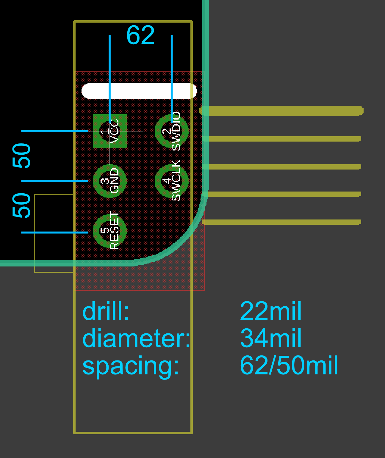
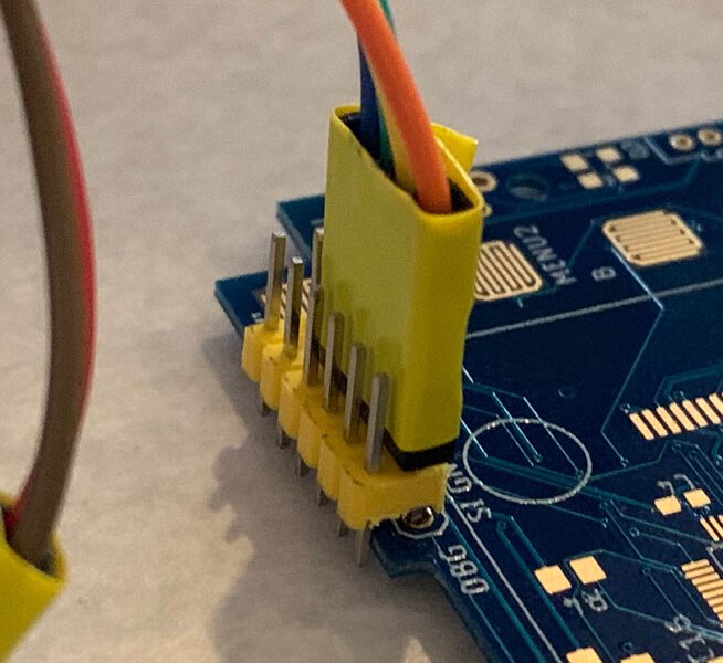
The idea is to use a standard 2x5 pin 0.05” IDC ARM-Cortex debug connector and plug in a male 0.05” header into it (a male 0.05” IDC could be also used, but they are harder to find). Then we put 22mil holes on the PCB with standard 50mil pin spacing, but 62mil row spacing. The male pins lock into the holes.
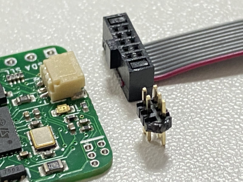
The restricted area (where the plastic from the header touches the PCB) is only about 5x3mm, and is usually further reduced by placing the connector in the corner of the board. Further, no components higher than 2mm can be placed under the connector itself (most small passives fit). We use the following pinout:
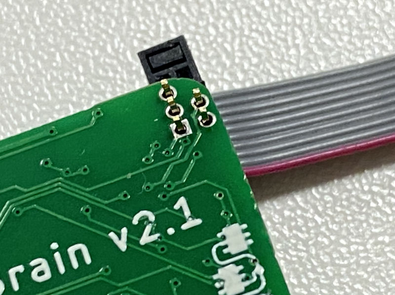
The white line on the silk shows the side of the PCB where the connector should be plugged in, and also the side where the red wire on the ribbon cable is. Note that it is impossible to plug it incorrectly. Libraries for PCB design software will be made available in the GitHub repo. Currently, there’s one for EagleCAD.
RESET pin
Pins 1-4 are the same as on Cortex connector. Unfortunately, Cortex connector places nRESET line on pin 10, which is way out. We instead use pin 5 for RESET (which is GND on Cortex connector). To make this work, you’ll need a custom cable.
If your debugger doesn’t use Cortex connector (or has the big 20-pin 100 mil connector), you can make a breakout cable. If your debugger use the 10 pin Cortex connector, you can make a Cortex cable that connects pin 5 to pin 10.
Breakout cable
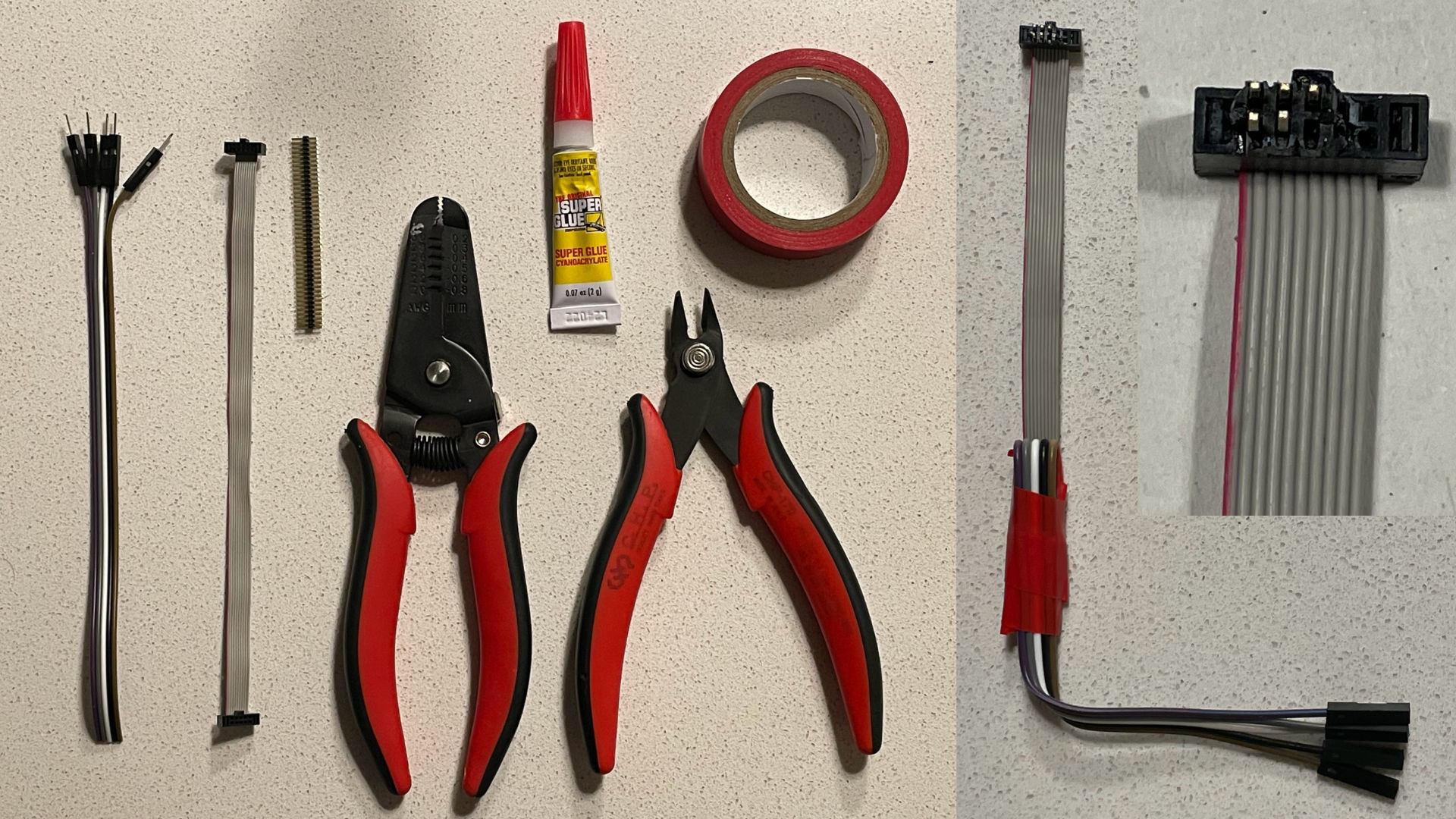
You will need a 10-pin IDC cable, whatever cables you need on the other side of the breakout, a 50 mil double row male header, wire cutters, insulation strippers, insulation tape, and glue.
Cut the IDC cable in half. You will the half with the notch facing outside (also see the picture of assambled cable above). Separate the first 5 wires, counting from the red write number 1.
Strip the insulation from the wires.
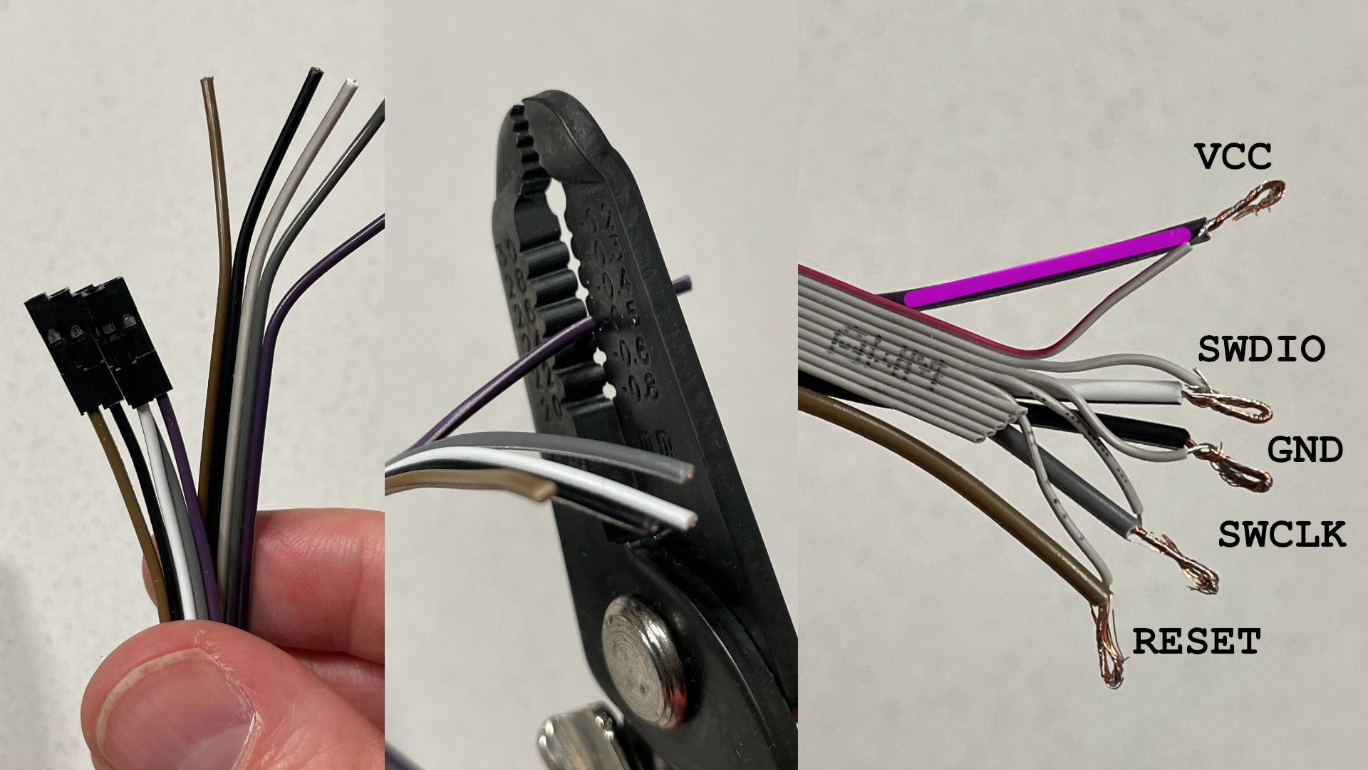
Strip insulation from the other side of your breakout, and twist the wires together. The picture above indicates the pinout.
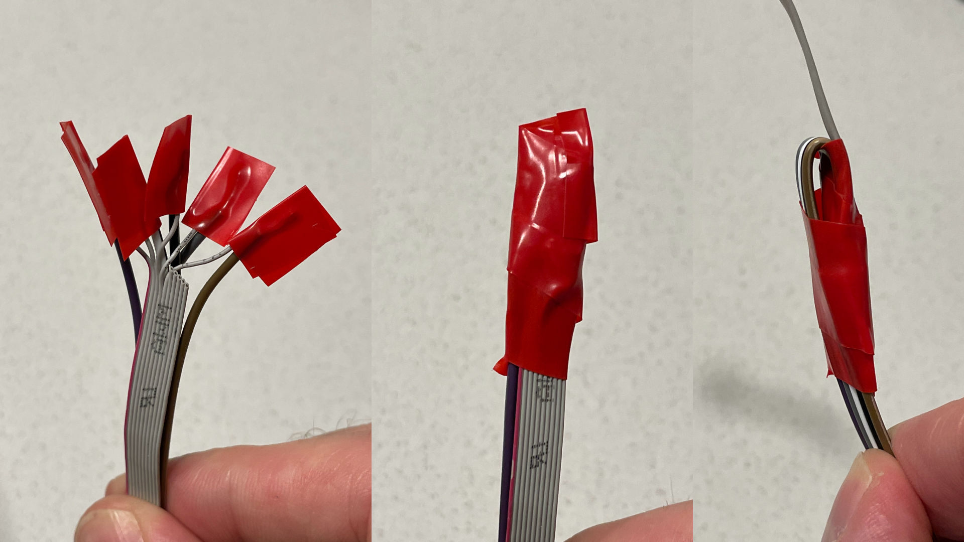
Put electrical (insulating) tape around each twisted wire, then around the all wires together, then bend one of the cables 180 degrees, and put tape around the whole thing.
Now, go to Target end section to finish the cable.
Cortex cable
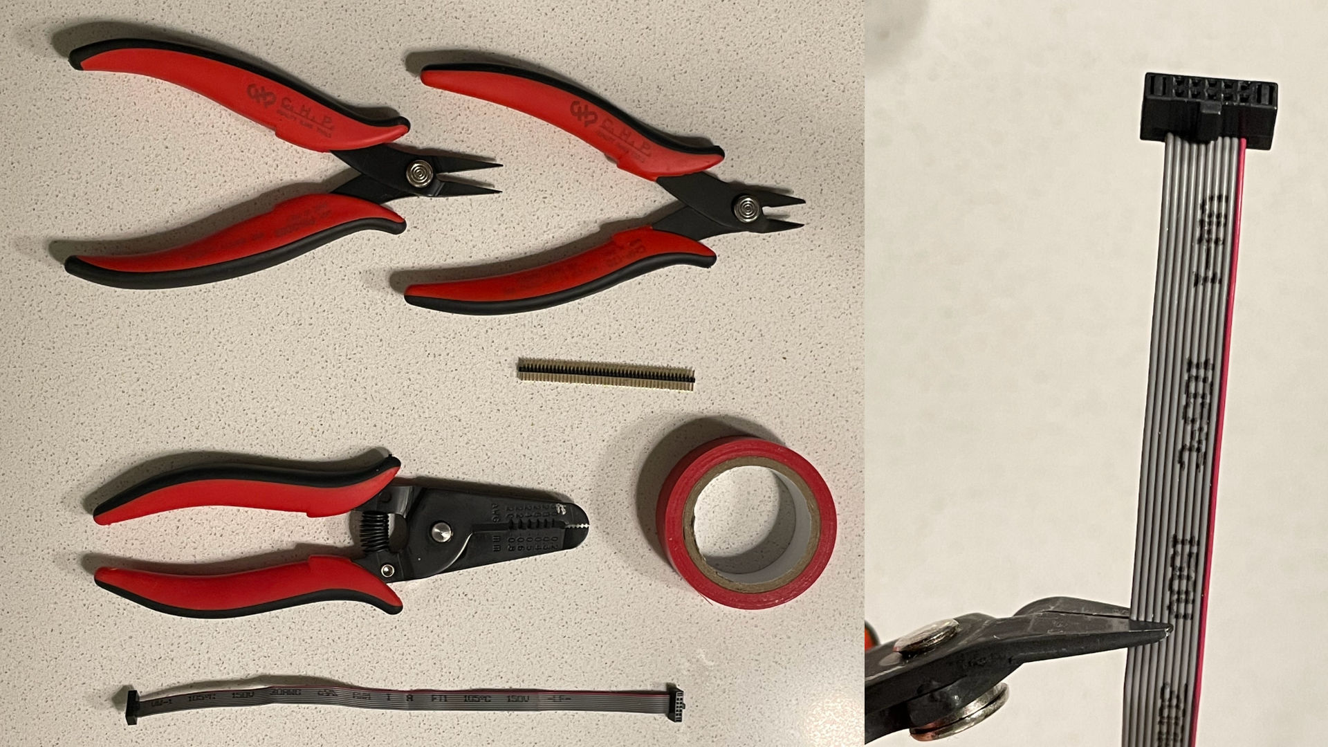
You will need a 10-pin IDC cable, a 50 mil double row male header, wire cutters, insulation strippers, insulation tape, and glue. Pliers are also useful.
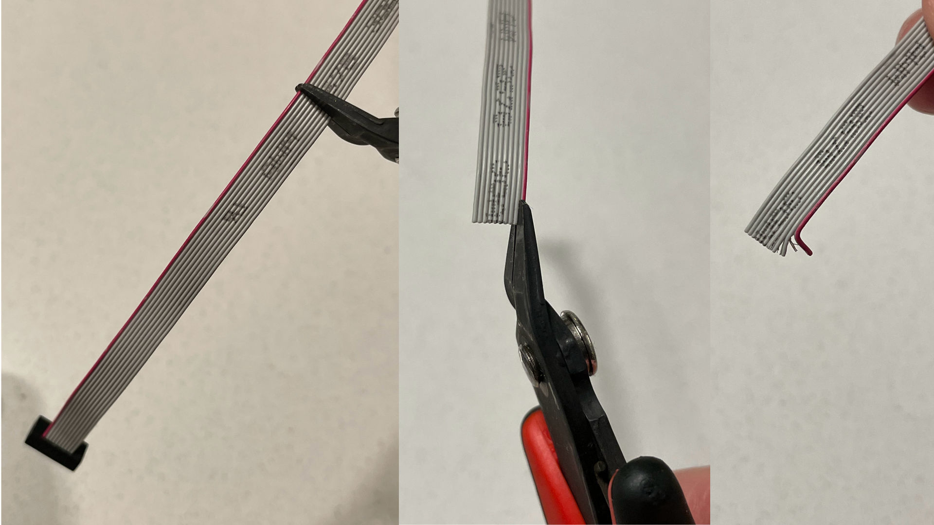
Cut wires 6-10 of the cable (this is exactly half the cable; red wire is number 1), around 50mm from the debugger side of the cable (with the notch facing inside). You need to be careful, not to cut wire number 5 here.
If you don’t care about connecting RESET line, you can just cut wires 5-10, and go directly to Target end section.
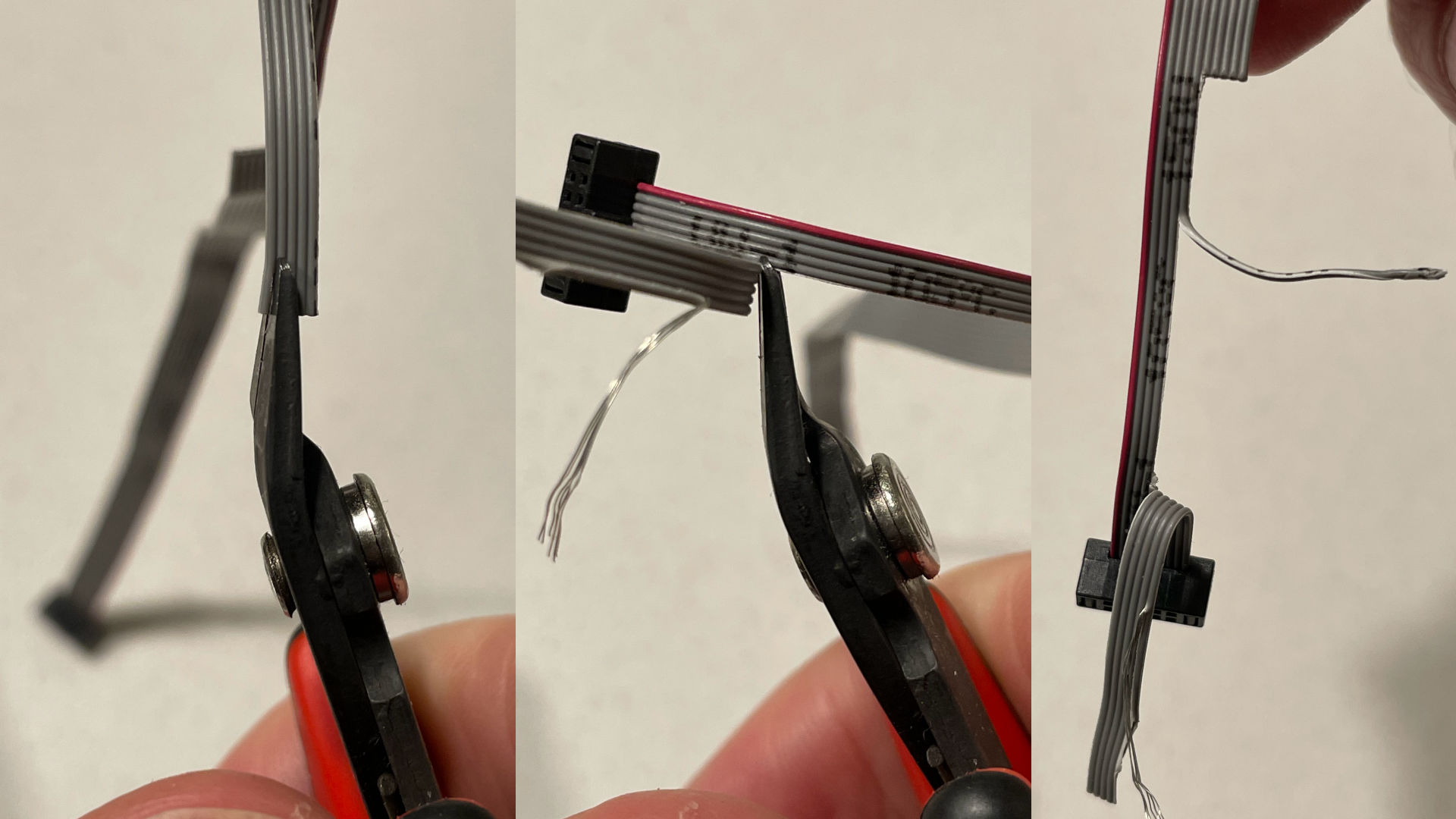
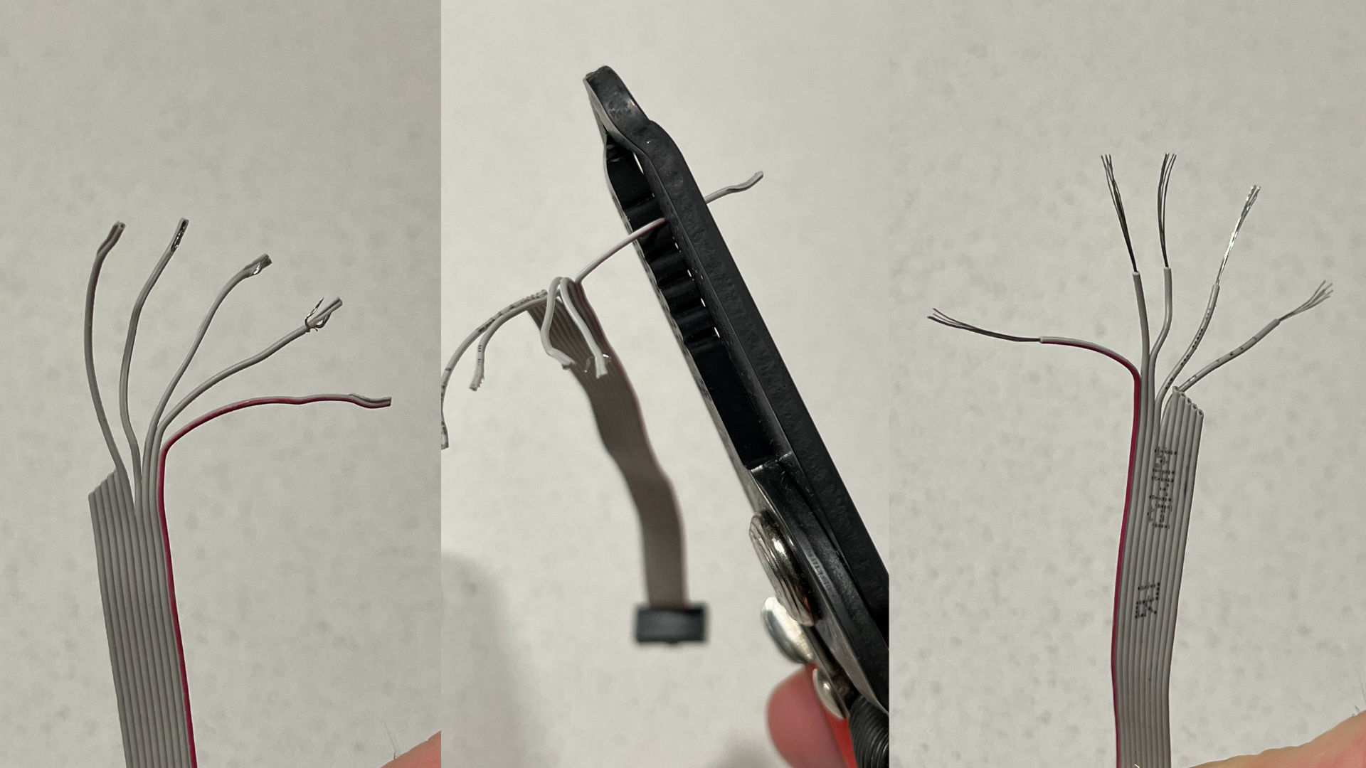
Pull wires 6-10 almost all the way towards the debugger connector. Then, separate wire number 10. It may happen that it will go out of insulation - don’t worry about this. Then, cut wire number 5, around 10mm from the debugger connector. Then, separate it.
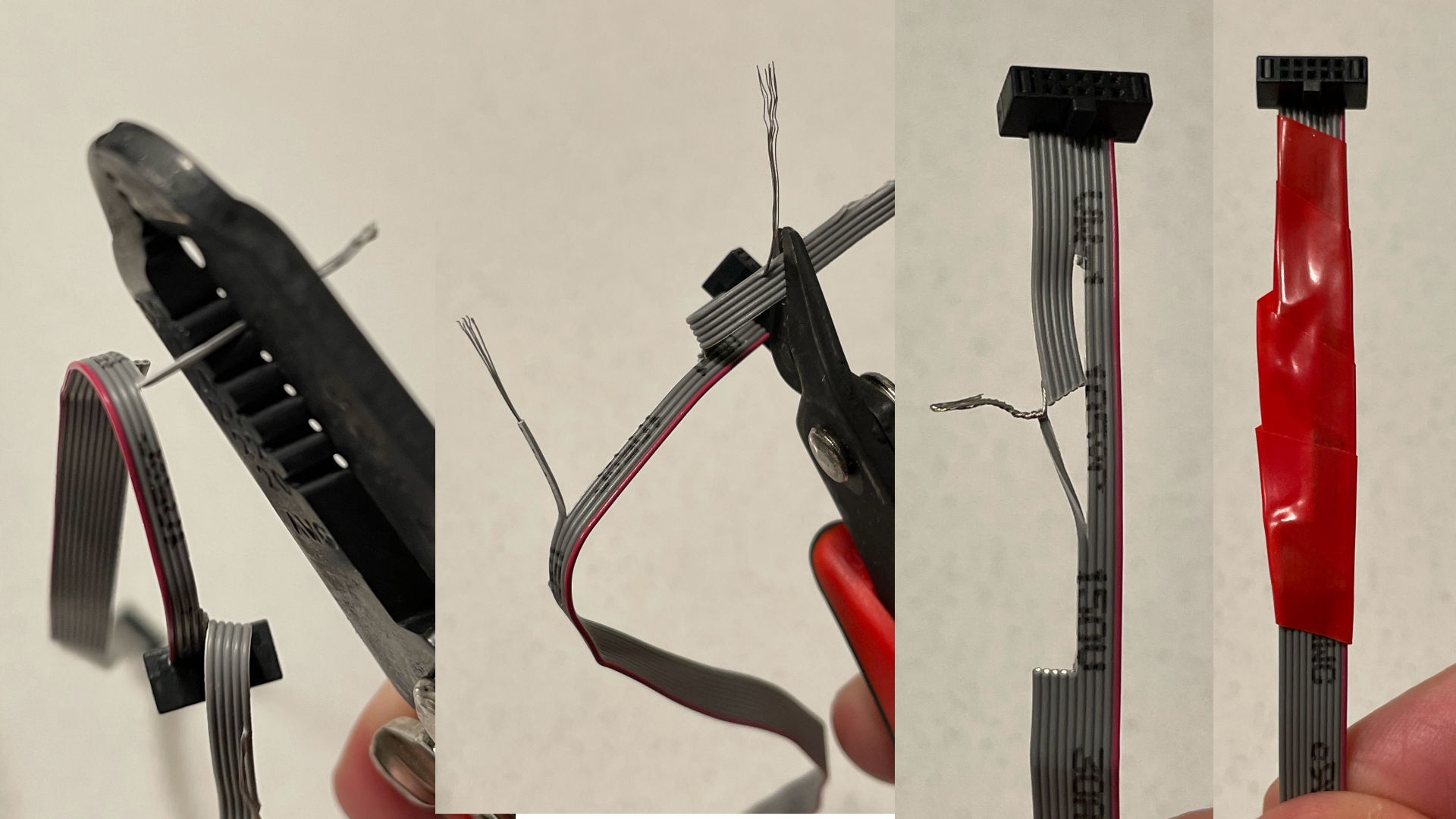
Remove insulation (if any left) from wires 5 and 10. Twist them together. Wrap the whole thing in electrical tape.
Target end
This section is common to both breakout and Cortex cable, and describes how to prepare the end of the cable that goes in the target PCB.
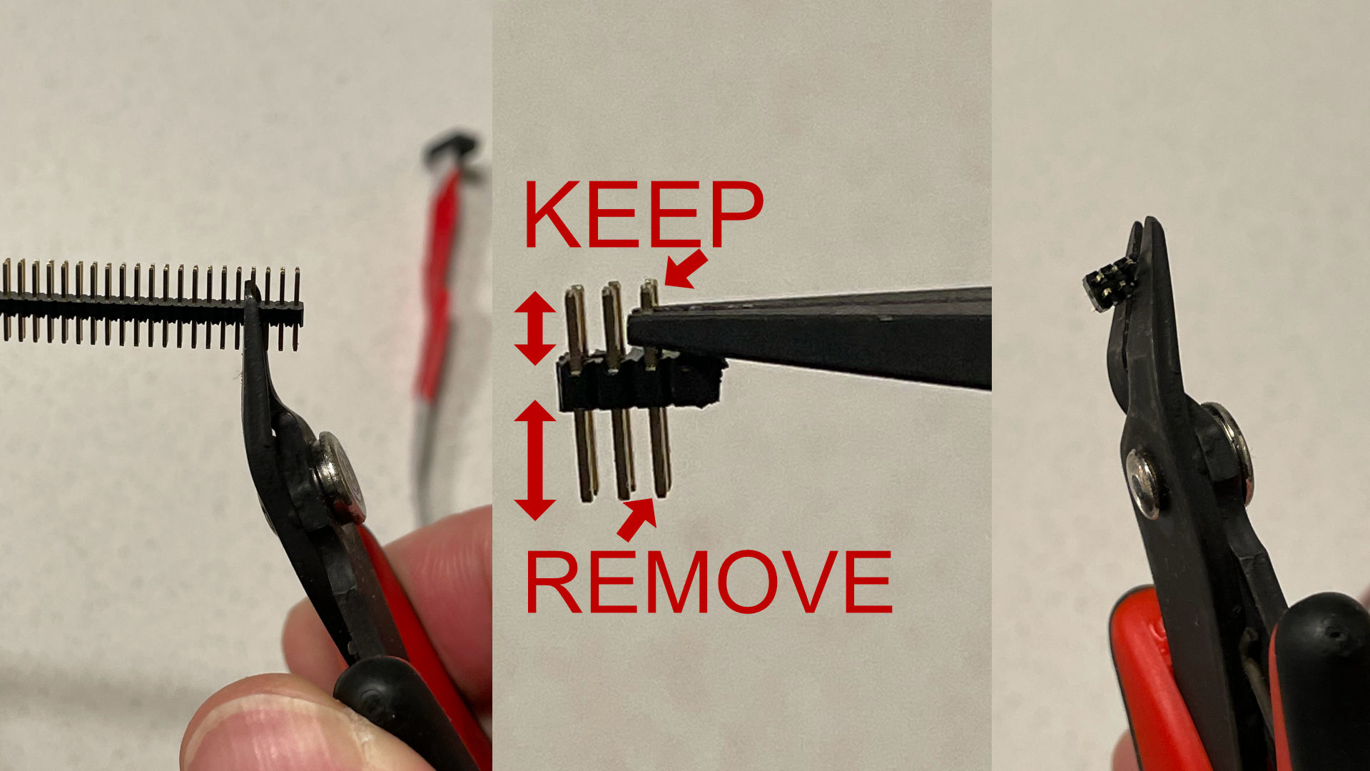
Cut 3 double rows from a male 50 mil header. You may want to cut 4 rows and remove the excessive pins (the plastic often breaks at the pin boundary). Then, remove pin number 6 - if you hold the header with the longer side (which will go into the IDC connector) down, it’s the right-most one, closest to you. Finally, remove excessive plastic.
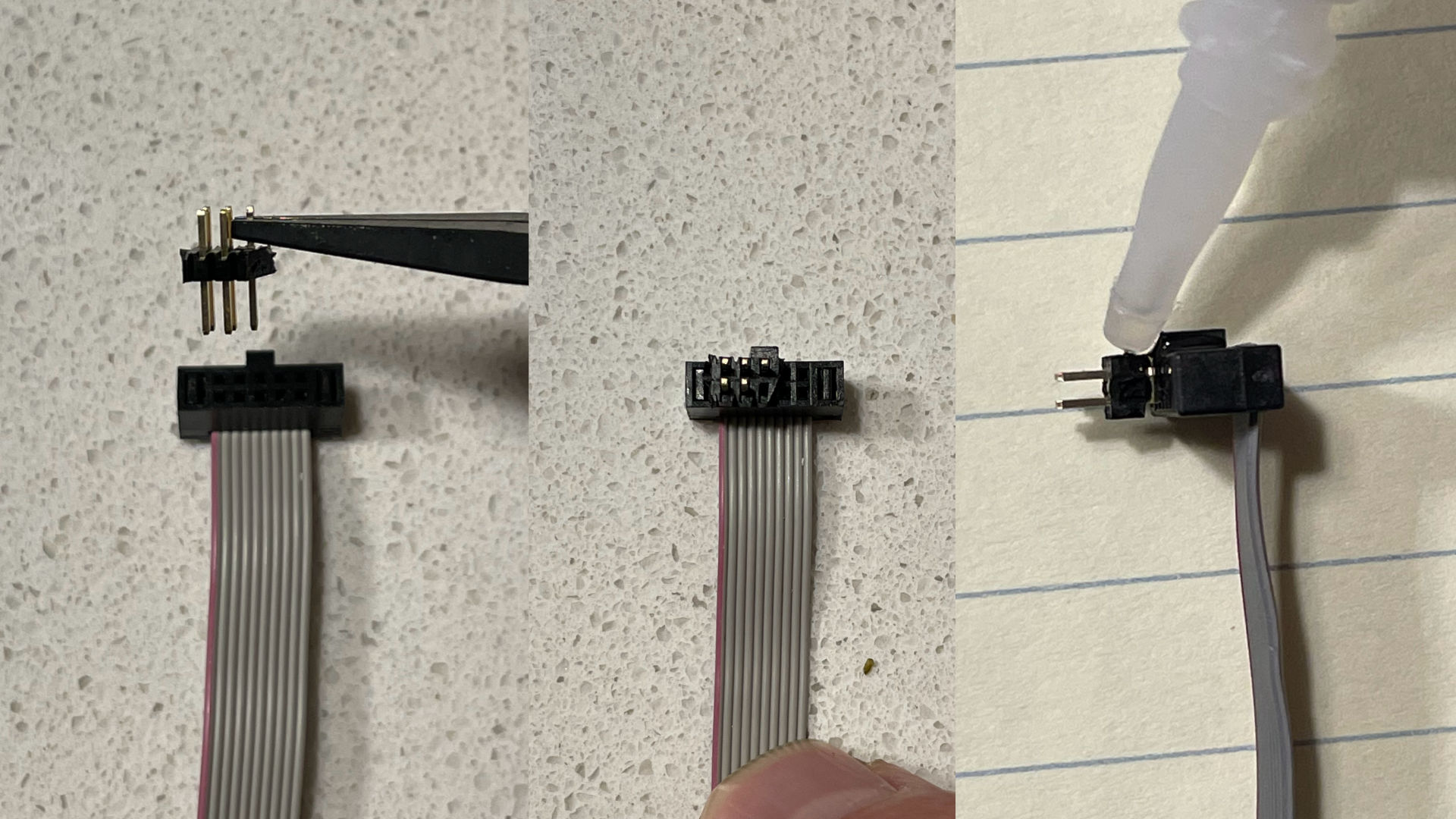
Now, insert the header into the connector, aligning the left side with the red wire. There should be 3 pins on the outer edge and 2 on the inner. You can test your cable now, before gluing - the header will likely stay in PCB when you pull out the cable, which is why we’re glueing. After testing, pull out the header out slightly (around 1mm), put a drop of glue in the gap, and then press the connector back in. Leave it to dry for a few minutes (it will stick to PCB if it doesn’t dry!).
You’re done!
Bonus
With either of the cables, you may want to add a momentary switch connecting RESET (pin 5) with GND (pin 3).
You can also use 6 pin (or 8 pin) IDC connector, instead of 10 pin one, if you happen to have it.
Pogo-connector
It’s also possible to create a connector with pogo pins for quick programming of a number of devices or use in a test rig.
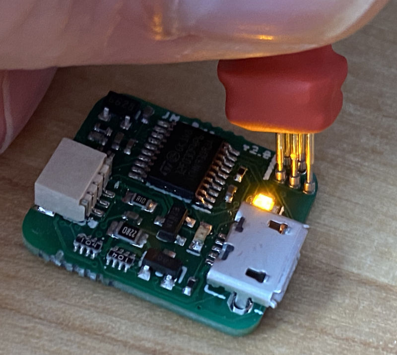
Use P50-E2 0.68mm diameter pins (head diameter of 0.9mm).
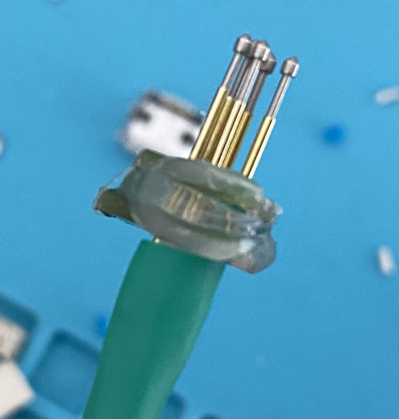
You can use two Hack-connector XS PCBs to hold the pins together, but you will need to order the holes a little bigger.
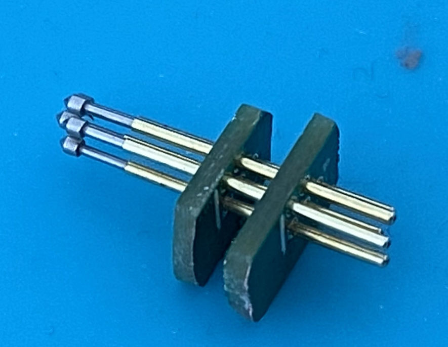
Once everything is in place, use glue gun or similar to secure the pins to the PCBs.
Hack-connect classic
Use a standard 0.1” spacing header holes with 40mil drill and place them so that the middle of the holes are exactly 0.1” from the edge of the board. Then use a two-row male header, and plug it into the holes on the short side and connect female jumper cables on the long side. The header will bend a little, forcing good electrical connection. You usually want to plug it starting from the edge.
Two row connector
Like the above, but use castellated holes for the second row of pins.
Pinout
The recommended pinout of one row header:
GND SWCLK 3V SWDIODo not put 3V and GND on opposite ends, since plugging the connector the wrong way would cause -3V to run through MCU.
You can add another GND connection to the right to make the plug symmetric as far as power is concerned. If you want to add a RESET pin, or a logging pin (possibly SWO, but can be custom as well), also add it to the right.
Note that with the two row cable plugged into a one row of holes, it only matter if you plug it in from the top or bottom of the board, which is quite easy to notice. Rotating the connector will result in no electrical connection.
Credits
Various pieces of the idea came from Steve Hodges, Jonny Austin, Michal Moskal, and James Devine.